PLASMA CUTTING GUIDES

The combination of cut quality, productivity, operating cost, and versatility make plasma today's most popular industrial cutting process.

Home / PLASMA CUTTING GUIDES
  • PLASMA SYSTEM COMPONENTS
  • WHAT IS PLASMA
  • PLASMA ATTRIBUTES
  • CUTTING APPLICATIONS
  • Contact
PLASMA SYSTEM COMPONENTS
  • A basic plasma cutting system includes the following components:

  • Power supply – A constant current DC power source. The open circuit voltage is typically in the range of 240 to 400 VDC. The output current (amperage) and overall kilowatt rating of the power supply determines the speed and cut thickness capability of the system. The main function of the power supply is to provide the correct energy to maintain the plasma arc after ionization.

  • Arc starting circuit – In most liquid-cooled torches of 130 amps and higher, this is a high frequency generator circuit that produces an AC voltage of 5,000 to 10,000 volts at approximately 2 MHz. This voltage creates a high intensity arc inside the torch to ionize the gas, producing the plasma. Rather than the high frequency starting circuit above, air plasma torches typically use a moving electrode, or “blowback start” technology to ionize the gas.

  • Torch – This serves as the holder for the consumable nozzle and electrode, and provides cooling (either gas or water) to these parts. The nozzle and electrode constrict and maintain the plasma jet.
WHAT IS PLASMA?

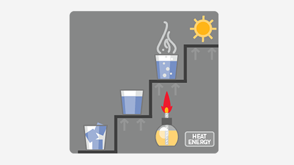
Plasma is the fourth state of matter. We normally think of three states of matter: solid, liquid and gas. For a common element, water, these three states are ice, water and steam.


The difference between these states is their relative energy levels. When you add energy in the form of heat to ice, the ice melts and forms water; if you add more energy, the water vaporizes and becomes steam. If you were to add considerably more energy to the steam – heating it to about 11,700° C – the steam would break up into a number of component gases, and would become electrically conductive, or ionized. This high energy ionized gas is called plasma.


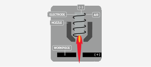
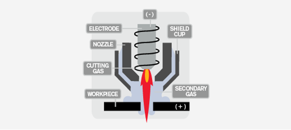
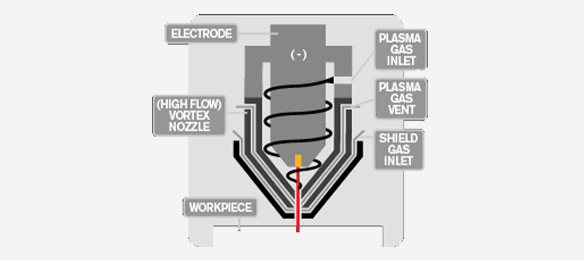
A plasma cutting system uses a plasma stream to transfer energy to a conductive work material. The plasma stream is typically formed by forcing a gas such as nitrogen, oxygen, argon — or even air — through a narrow nozzle. An electric current produced by an external power supply adds sufficient energy to the gas flow to ionize it, turning it into a plasma arc with temperatures approaching 40,000˚ F. The plasma arc cuts the workpiece by melting it, and blows away the molten metal.

PLASMA ATTRIBUTES

Material type

· Any electrically conductive metal, including stainless steel and aluminum

· Can handle rusted, painted, and expanded metal


Cut quality

· Tolerances in the +/- 0.38 mm to 0.5 mm (+/- 0.015” to 0.020”) range with average edge angularity of 2° to 3° on steel less than 10 mm (3/8”); 1° on 12 mm to 38 mm (1/2” to 1-1/2”) steel; less than 1° on 50 mm (2”) steel

· Narrow heat affected zone, typically less than 0.25 mm (0.010”)

· Correct choice of process and gases will produce minimal edge hardening, allowing excellent weldability

· Relatively smooth edges with smooth torch motion

· Minimal dross (resolidified metal) on steel up to rated production capacities

* Tolerances will vary depending on material type and thickness, part geometries, and overall design and quality of the cutting system. The tolerances listed here are generally accepted tolerances assuming the use of a good quality cutting table with good motion capabilities. Different cutting tables will provide different outcomes even if equipped with the exact same cutting components.


Ideal thickness

· Mild steel, stainless and aluminum from 26 gauge up to 50 mm (2")

· Capable of cutting stainless and aluminum up to 182 mm (6-1/4"); some secondary work will be required


Productivity

· Faster than laser on 6 mm (1/4”) and thicker materials

· Faster than oxyfuel up through 50 mm (2”)


Operating cost

· Low cost per part on all materials and thickness through 50 mm (2”)

· Low service and maintenance requirements


Capital equipment cost

· Medium – higher than oxyfuel, lower than laser and waterjet


Portability

· Highly portable, lightweight inverter designs on the air plasma systems

· Today’s systems are designed for good performance on a generator

· Some systems include built-in air compressors


CUTTING APPLICATIONS
  • · Straight cutting
  • · Bevel cutting
  • · Gouging
  • · Hole cutting
  • · Extended reach cutting and gouging
  • · Fine feature cutting
  • · Marking

TYPES OF PLASMA

Conventional Single Flow Plasma


  • This process uses two gases, a plasma gas and a shield gas. In systems under 125 amps, air is often used as both plasma and shield. The advantage of the shield technology is that it electrically insulates the nozzle from contact with molten metal blowback from piercing, and also allows for drag cutting in hand applications. Further enhancements (conical flow technology) have improved cutting performance and nozzle life on some systems.

Dual Flow Plasma (Shielded)


This process uses two gases, a plasma gas and a shield gas. In systems under 125 amps, air is often used as both plasma and shield. The advantage of the shield technology is that it electrically insulates the nozzle from contact with molten metal blowback from piercing, and also allows for drag cutting in hand applications. Further enhancements (conical flow technology) have improved cutting performance and nozzle life on some systems.


High Definition Plasma


In this process, a specialized nozzle design narrows the arc and increases energy density. Because of the higher arc energy, high definition plasma achieves superior cut quality on materials up to 50 mm (2”) with superior cut edge angularity, narrower kerf and higher cut speeds than conventional plasma cutting technology. It's not uncommon with these systems to achieve cut part accuracies within the +/- 0.25 mm (0.010") range.


Today’s high definition systems allow very high levels of automation, and are intended for automated applications only. In the most advanced systems, virtually all of the machine operator’s expertise (required to get good cut quality on earlier plasma systems) is essentially captured in the CAM software that manages the day-to-day cutting operations.


With high definition plasma, cut holes are round and have virtually no taper. Edges are square and dross free. Cut-to-cut cycle times allow much higher levels of productivity. A single-plasma system can cut material thicknesses from thin gauge to over 182 mm (6”), using the same torch. The torch can cut and mark the plate through he same nozzle orifice.


LET'S STAY IN TOUCH
Get updates on sales specials and more
FOLLOW US:
We want to hear from you!